Interchangeable and Compact Battery Design
Safety Warning
This article documents my engineering work on a lithium battery pack. These components present a serious fire risk in the event of a short circuit, overcharge, or mechanical damage. This document is not a tutorial. Do not handle batteries without proper PPE and a thorough understanding of the risks involved.
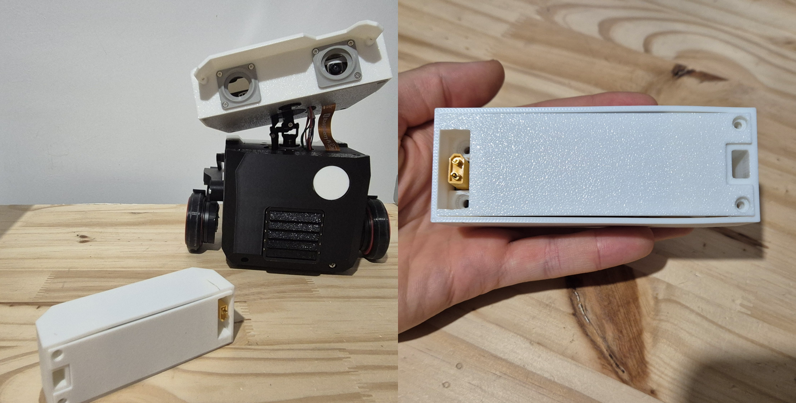 Figure 1: the finalized battery pack in its 3D-printed enclosure.
Specifications and Needs
Power supply is a critical point for the robot: actuators generate significant current spikes, while the chassis imposes strict size constraints. These two requirements conflict with each other, and it is this trade-off that shaped the entire design.
The goal was to design a removable, secure, and plug-and-play pack with a single connector handling both charging and discharging.
Selected specifications:
- Nominal voltage: 11-12 V (3S architecture)
- Discharge current: capable of handling motor start-up current peaks
- Ergonomics: a single power connector, with no balancing port accessible to the user
- Maximum footprint: 84 × 36 × 29 mm
- Safety: built-in protection against short circuits, overcharging, and deep discharge
Technology Study and Choices
Why Reject the Li-Ion 18650 / 21700 Standard
Common practice in DIY pack design (e-scooters, e-bikes) is to assemble cylindrical 18650 or 21700 cells by spot welding with nickel strips.
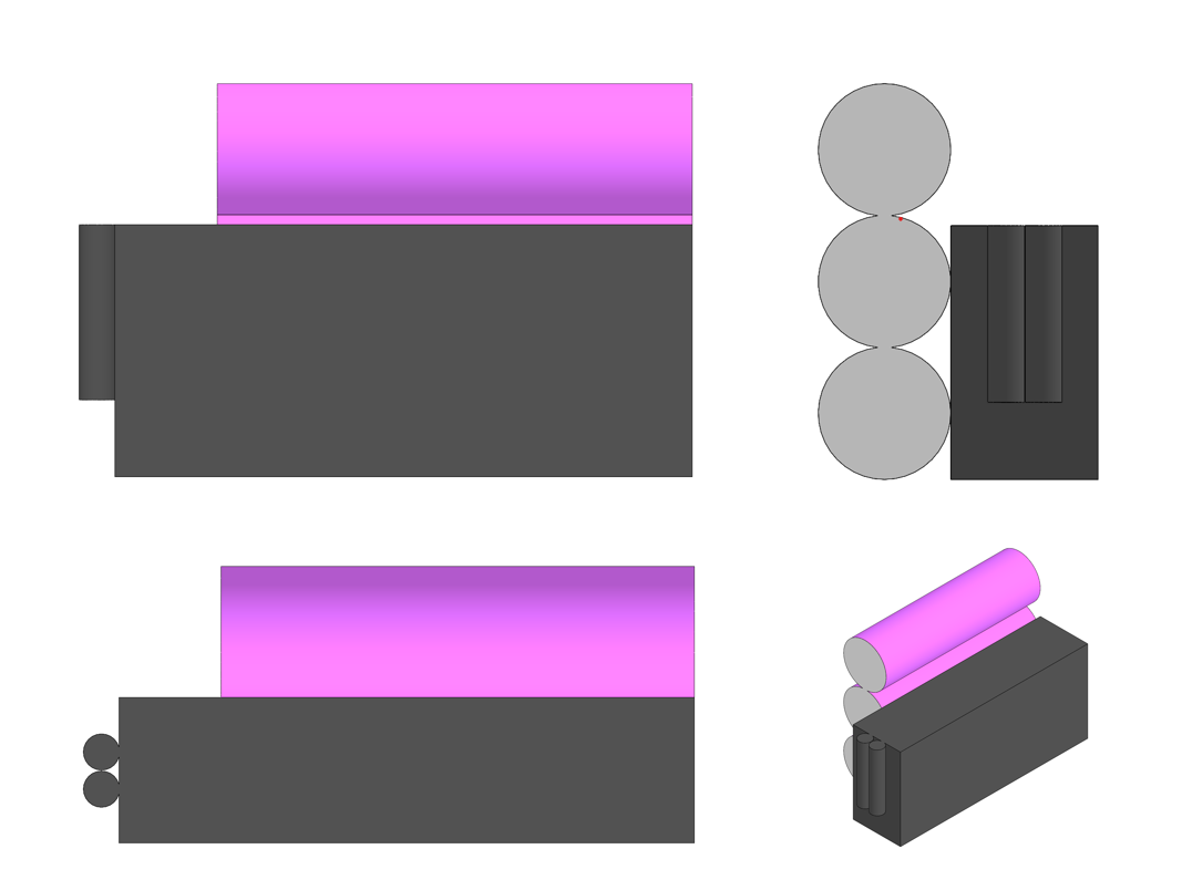 Figure 2: size study. The cylindrical format creates too much wasted space in my chassis.
Reaching 12 V requires a 3S configuration, meaning three cells in series. Stacked, the cylinders leave unusable gaps between them: the volumetric efficiency became incompatible with the available space.
The Chosen Solution: RC LiPo and Embedded Electronics
I chose a lithium-polymer (LiPo) cell of the type used in drones and RC vehicles.
- Prismatic format: the flat geometry fits the available volume without waste
- Pre-assembled pack: no spot welding, so no thermal risk to the cells
- Generous C-rating (30C): a discharge rate well above the nominal requirement, ensuring minimal heat generation in real use
- Component selected: Batterie LiPo 3S 11,1 V 1300 mAh, 15 Wh, Vapextech, VPLP014FD
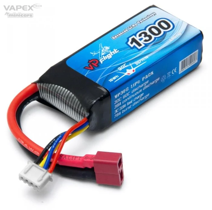 Figure 3: the base cell used, before modification.
Details on the 12 V voltage selection are covered on the power architecture page.
Electrical Design: BMS Integration
A 3S LiPo comes from the factory with two harnesses: a power cable for discharging, and a four-pin balance cable for monitoring each cell during charging.
My specification requires a single connector. The balancing function therefore had to be internalized inside the pack, which is achieved through an integrated BMS (Battery Management System).
I chose a generic, unbranded 3S 25 A BMS module sourced from AliExpress.
Role of the BMS Circuit
- Balancing: balance the 3 cells at the end of the charge. Voltage drift between cells degrades the chemistry and eventually destroys the pack.
- Discharge cutoff: the BMS opens the circuit when any cell drops below 2.8 V (typ.), and restores it above 3.0 V. This is a hardware limit of the protection module, not a design choice: 2.8 V is already deep into the damaging range for LiPo, so a software cutoff at 9.6 V (3.2 V per cell) acts first and keeps the BMS as a last-resort safety net.
- Overcurrent protection: the module trips at 60 A (typ.) with a 1 s delay, and reacts within 300 µs on a hard short. Continuous current is rated at 25 A in both charge and discharge — the limiting figure for normal operation.
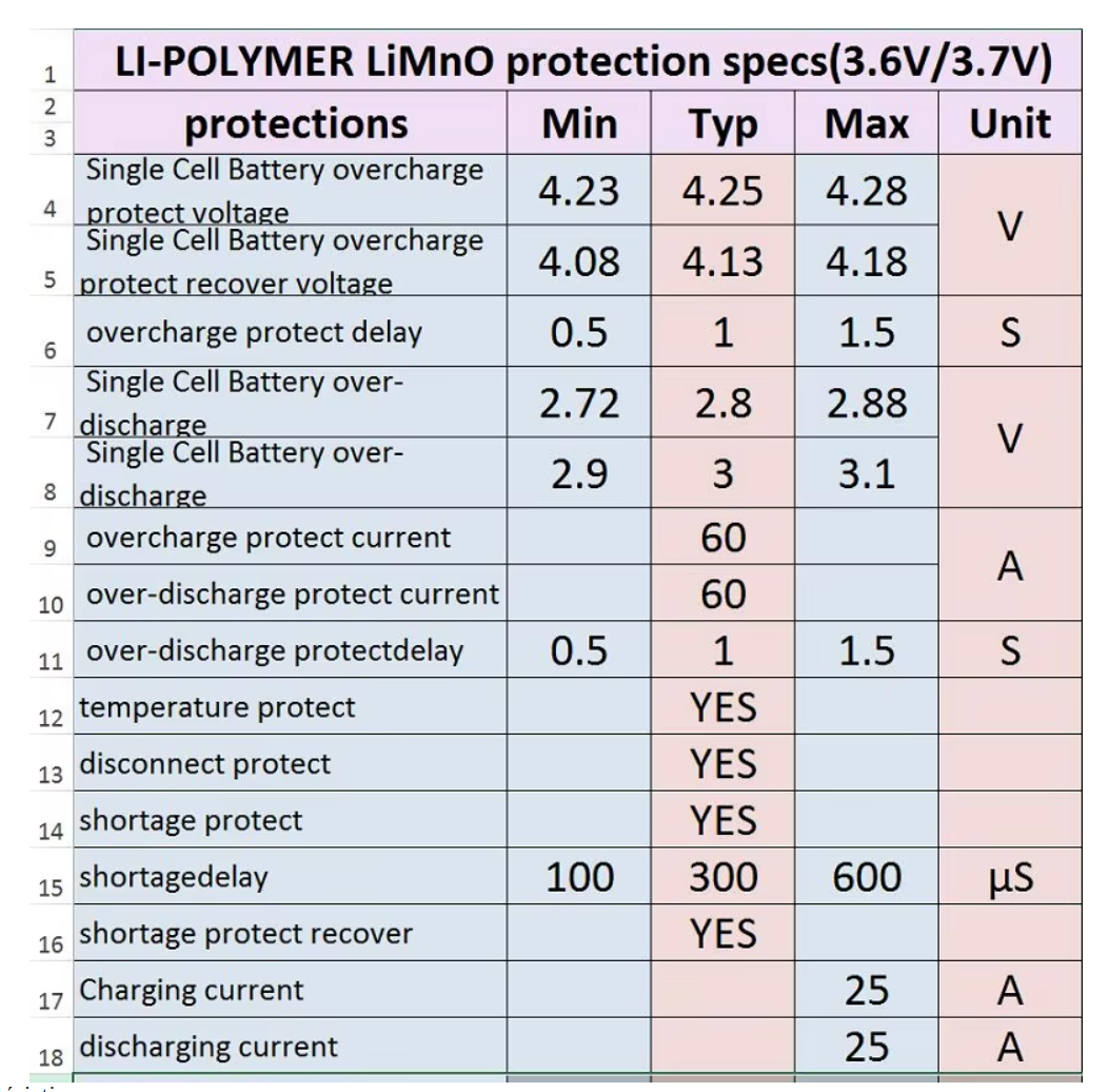 Figure 4: BMS Safety and threshold values.
BMS Wiring
Below is the schematic produced to modify the commercial battery and interface it with the BMS.
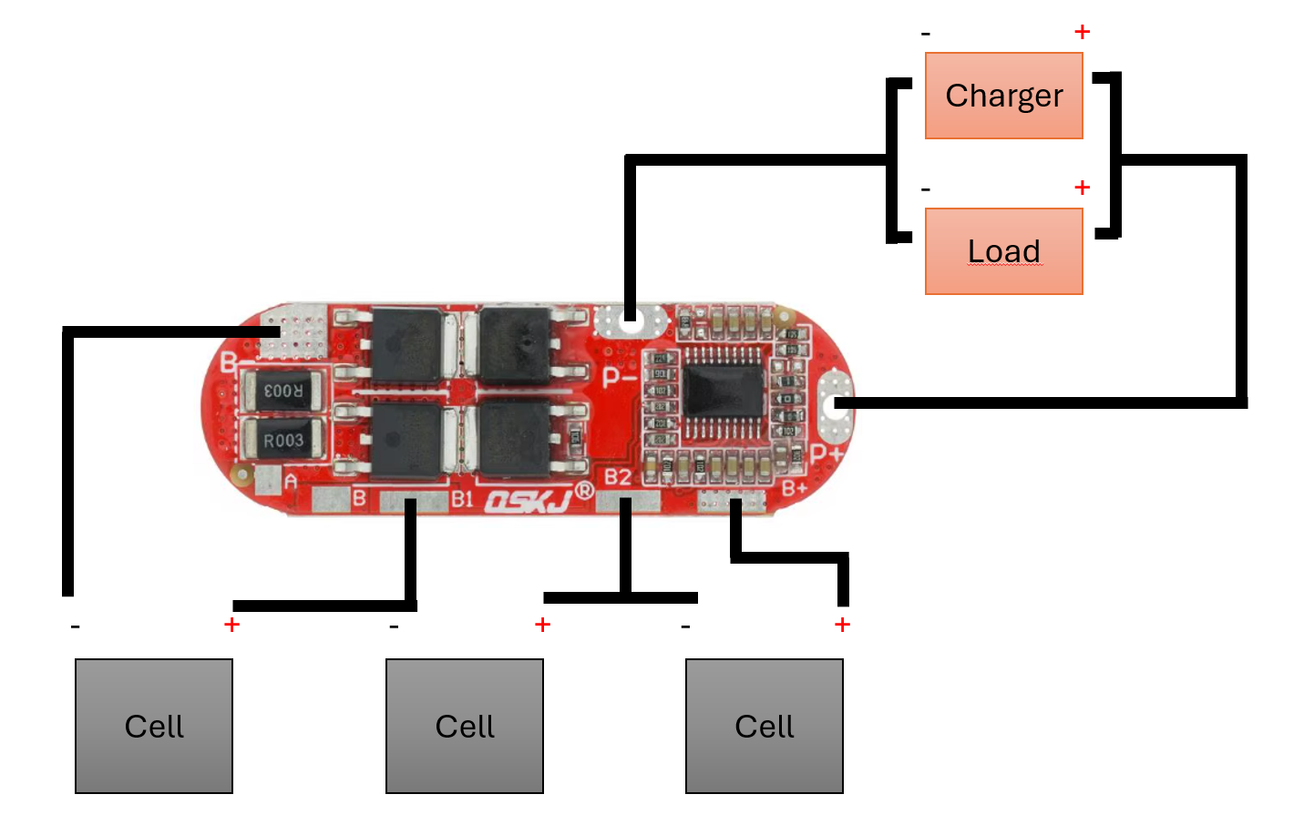 Figure 5: connection of the balancing leads (B-, B1, B2, B+) and power outputs (P-, P+) to the BMS.
Mechanical Design of the Enclosure
A LiPo is soft and very sensitive to puncture: in a mobile robot, it cannot be left bare. I therefore designed a custom rigid shell in CAD.
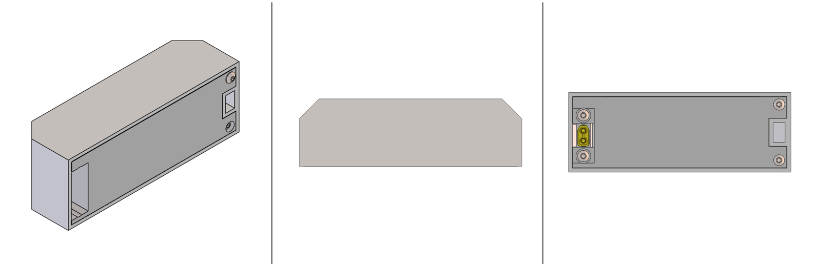 Figure 6: 3D model of the enclosure.
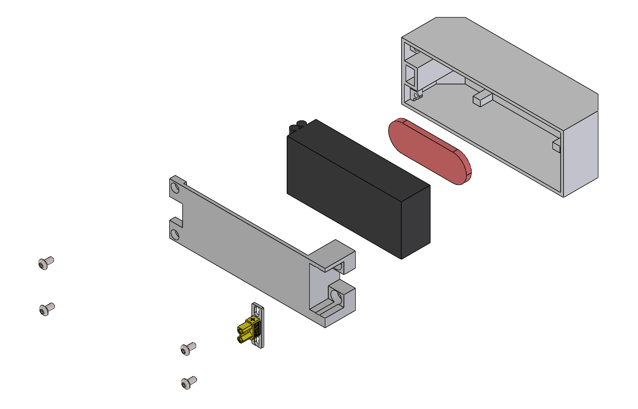 Figure 7: exploded view of the mechanical assembly.
Design choices:
- Material: prototype in PLA for iteration speed.
- Tolerances: tight fit to eliminate vibration, but never compressing the LiPo Battery. Different LiPo Batteries (same model) have slightly different dimensions.
- Connector: XT30 screwed into the shell. It serves as a mechanical key and ensures a firm connection with the chassis
- Fixation: XT30 on the first side and on the second side of the battery it's a 3D-printed locating pin that fits into the battery to hold it in position.
Assembly and Prototyping
Assembly requires great care: the balance leads are thin, close together, and an accidental contact during soldering is enough to cause a short circuit.
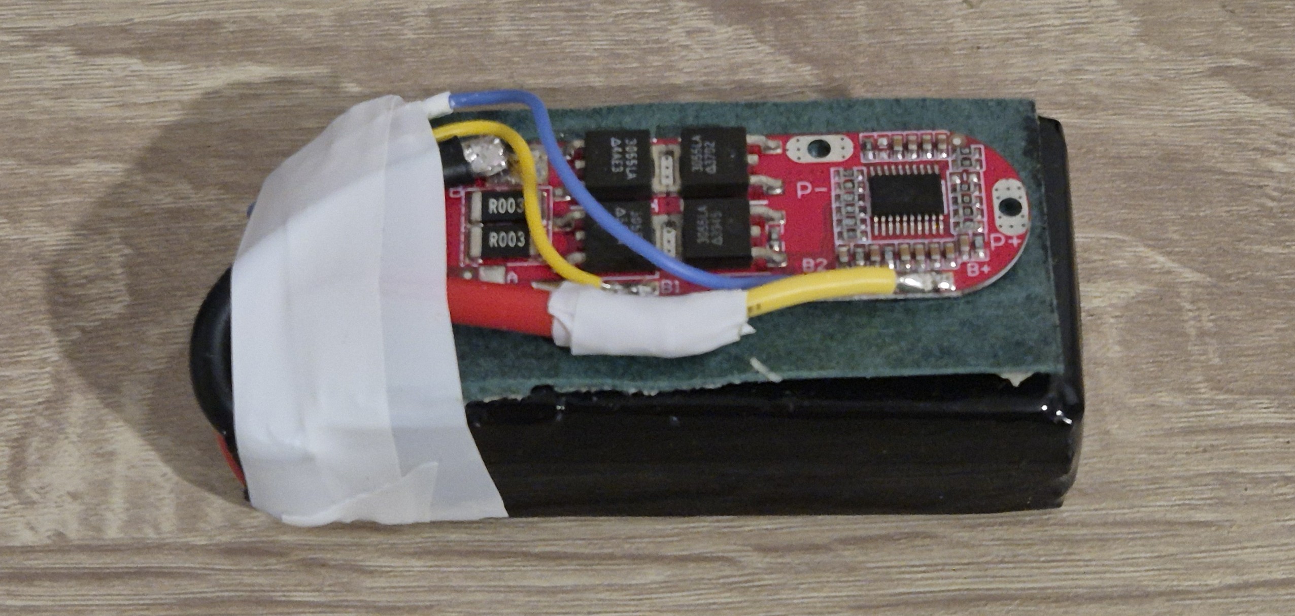 Figure 8: soldering the cell leads onto the BMS
Between the BMS and the battery I added fish paper, an insulating tape specially developed for the use case. In green in the figure 8.
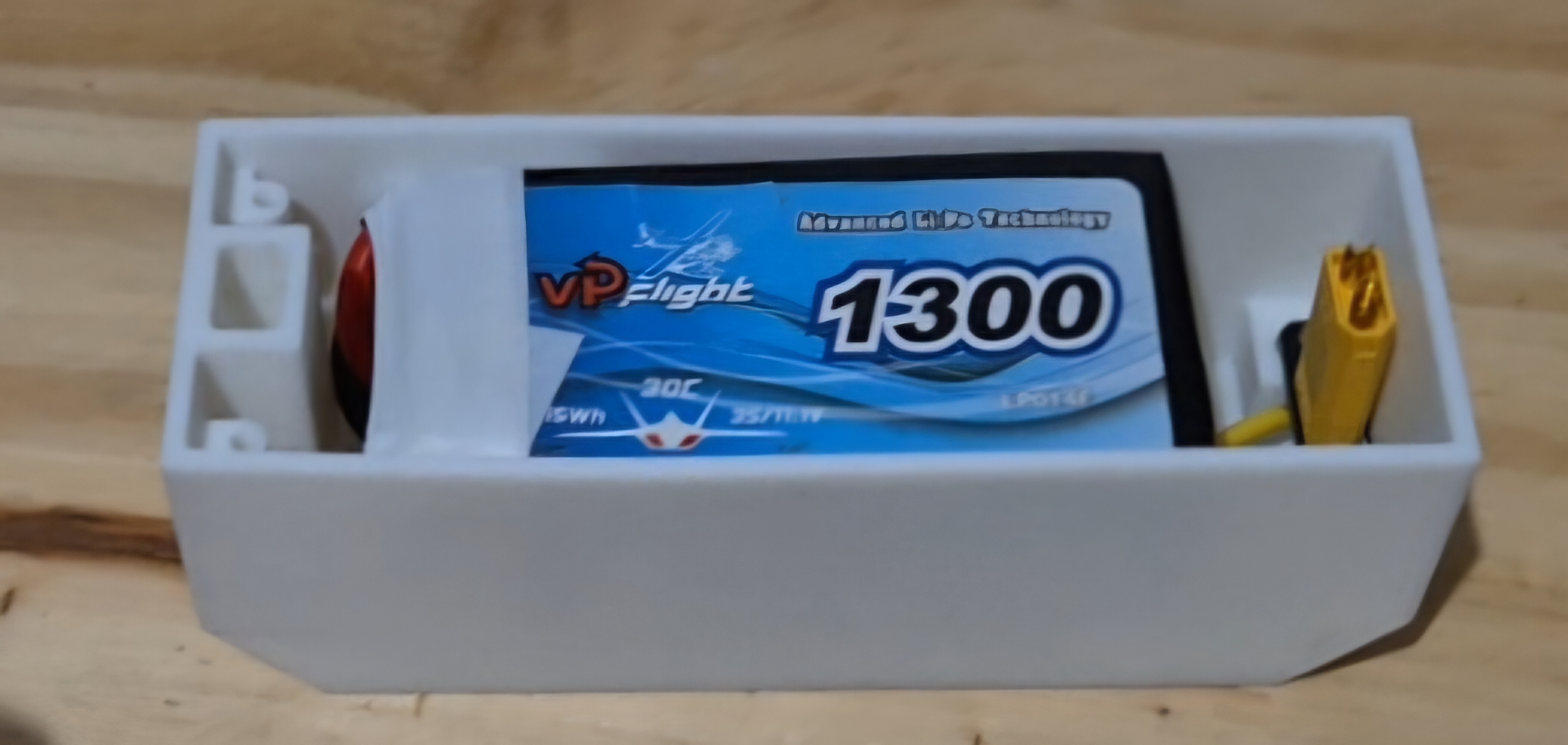 Figure 9: cable routing and component placement in the printed shell.
Testing and Validation
Three tests were conducted before final integration into the robot.
- Cell voltages: multimeter measurement on each cells 24 hours after the assembly to validate that the cells have not been damaged: OK
- Charge cycle: Several cycles of discharge and charge via the single connector, to validate balancing operation: OK
- Total weight: weighing of the complete battery: 151 g
Conclusion
This development transformed a raw RC battery into a simple to use and swappable battery pack, tailored to the dimensional constraints of the robot.